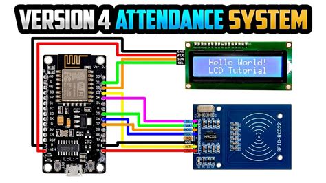
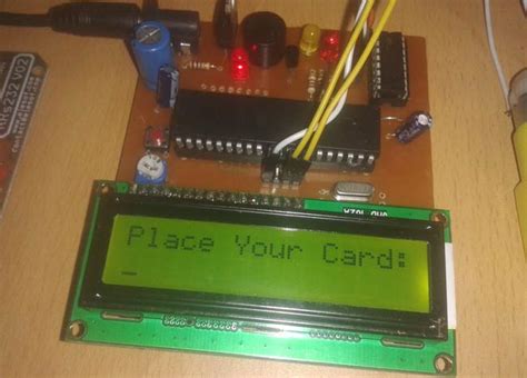
circuit diagram of rfid based attendance system Learn how you can make your own RFID based attendance system using Arduino and display the status of attendance on a 16x2 LCD. Find and press the “Connections” or “Network & Internet” option from the main Settings screen. F ind and pick the “NFC” option from here, or simply search for “tag” in your settings search bar if it is present. Simply flip .
0 · rfid based attendance system using nodemcu
1 · rfid based attendance system using 8051
2 · rfid based attendance system pdf
3 · rfid attendance tracking system
4 · rfid attendance system using esp32
5 · rfid attendance system using atmega32
6 · rfid attendance system pdf
7 · attendance monitoring system using rfid
$39.99
Here we will count the attendance of an authorized person by using RFID. We can divide the complete attendance system into different sections: reader section, control section, . This is a simple RFID based attendance system circuit diagram using ATmega8 Microcontroller and working process, source code.
This is the block diagram of our project RFID Based Attendance System using Arduino, RTC & LCD Display. Here Arduino UNO acts as a central processor for controlling all . Learn how you can make your own RFID based attendance system using Arduino and display the status of attendance on a 16x2 LCD. Circuit Diagram – RFID based Attendance System. Project Description. The full circuit diagram for interfacing RFID module to Arduino is shown above. The unique ID code in .
Here we will count the attendance of an authorized person by using RFID. We can divide the complete attendance system into different sections: reader section, control section, driver section and display section. Role of each section is shown in the below block diagram: Reader Section. In this project we have designed RFID Based Attendance System using Arduino UNO and RFID MFRC522 Module. This is a simple RFID based attendance system circuit diagram using ATmega8 Microcontroller and working process, source code.
This is the block diagram of our project RFID Based Attendance System using Arduino, RTC & LCD Display. Here Arduino UNO acts as a central processor for controlling all other components as input/output unit. Learn how you can make your own RFID based attendance system using Arduino and display the status of attendance on a 16x2 LCD. Circuit Diagram – RFID based Attendance System. Project Description. The full circuit diagram for interfacing RFID module to Arduino is shown above. The unique ID code in the RFID card is read by the circuit and the name of the corresponding person will be displayed on the 20 x 4 LCD display.
To built this RFID based Attendance System, we will need the following components: We can easily purchase all the components from the Amazon links below: Circuit Diagram & Hardware. The circuit for RFID based Attendance System using Arduino & SIM800L Module is very simple. I used Fritzing software to draw this schematic.

rfid based attendance system using nodemcu
This project implements an RFID attendance system using an ESP32 microcontroller, an RFID reader (MFRC522), and an OLED display. The system reads RFID card IDs and sends them to a server using HTTP requests for attendance tracking and logging. In this project, you will learn how to make IoT Based RFID Attendance System using Arduino Node MCU ESP8266 Arduino & Adafruit.io Platform using the MQTT broker. So we will use RFID MFRC522, Arduino Nano, and Node MCU ESP-12E Board . Circuit Diagram. Here is a full circuit diagram of our projects, when we scan the card the name of the person is displayed in the 20×4 LCD Display. the 20×4 LCD Display will be connected to the i2c Protocol and only 4 pin connection. GND . Here we will count the attendance of an authorized person by using RFID. We can divide the complete attendance system into different sections: reader section, control section, driver section and display section. Role of each section is shown in the below block diagram: Reader Section.
In this project we have designed RFID Based Attendance System using Arduino UNO and RFID MFRC522 Module. This is a simple RFID based attendance system circuit diagram using ATmega8 Microcontroller and working process, source code.
This is the block diagram of our project RFID Based Attendance System using Arduino, RTC & LCD Display. Here Arduino UNO acts as a central processor for controlling all other components as input/output unit.
Learn how you can make your own RFID based attendance system using Arduino and display the status of attendance on a 16x2 LCD. Circuit Diagram – RFID based Attendance System. Project Description. The full circuit diagram for interfacing RFID module to Arduino is shown above. The unique ID code in the RFID card is read by the circuit and the name of the corresponding person will be displayed on the 20 x 4 LCD display. To built this RFID based Attendance System, we will need the following components: We can easily purchase all the components from the Amazon links below: Circuit Diagram & Hardware. The circuit for RFID based Attendance System using Arduino & SIM800L Module is very simple. I used Fritzing software to draw this schematic.This project implements an RFID attendance system using an ESP32 microcontroller, an RFID reader (MFRC522), and an OLED display. The system reads RFID card IDs and sends them to a server using HTTP requests for attendance tracking and logging.
In this project, you will learn how to make IoT Based RFID Attendance System using Arduino Node MCU ESP8266 Arduino & Adafruit.io Platform using the MQTT broker. So we will use RFID MFRC522, Arduino Nano, and Node MCU ESP-12E Board .

rfid based attendance system using 8051
NFC WG 26 Reader and Writer Module has 1.97 in read distance, 30 mA to 50 mA operating current, and -13 oF to 176 oF working temperature. . Tags & Accessories GAOTek NFC WG26 Reader And Writer Module MFRC 522 .
circuit diagram of rfid based attendance system|rfid based attendance system using nodemcu